Week Three
Click the Arrow to Proceed to Project Page
Click the Arrow to Proceed to Project Page
PCB and soldering
The process: This week we were given some pre-designed circuit board schematics to mill using the Modela and assemble using surface-mounting techniques. While this process was superficially simpler than last week's since the designs were provided, it was my first time assembling electronic components and soldering, so I found it to be nontrivial.

Method:
After downloading the .png file of the board, I opened the fab module to start the milling process. In setting the x min and y min values, I found that it was convenient to try to line the board up as precisely as possible with the corner of the sacrificial layer and then exiting view mode to see how well my estimate of the position matched the actual position of the board. I used three pieces of double-sided tape to hold my board down. One thing to note is that the fab modules do not remember the x min and y min values between the traces and output settings. I forgot this once and almost had to start the process over. It is also important to change the final command line to USB0 instead of USB1 so that the computer is able to communicate with the milling machine.
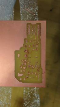
For the initial run, I started with the interior of the board and placed the 1/64th endmill piece in the machine. Since I did not know what the endmills were really supposed to look like, I assumed that the one I was using was intact. As you can see from the image above, this was not actually the case. In addition, in turns out that the set screws had been jammed into the piece by repeated misuse, so the endmill was able to wobble around in the machine. The combined effect of these issues is displayed below. While the board was being cut, instead of collecting a pile of dust, the board seemed to unravel into curly strips of copper.
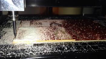
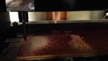
Once I had effectively milled the traces with a new endmill and corrected set screws, I switched the endmill to cut out the piece. With the 1/32 piece, it is much easier to discern whether or not the piece is intact. It is difficult during the milling process to figure out if things are running smoothly because the board becomes cloaked in a pile of dust, as shown below.

 s
s
Assembly
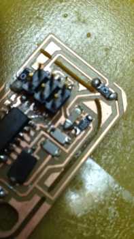
This was my first electronics assembly and soldering expedition. As it turns out, I found soldering very frustrating at first. While I attempted to use the flux pen, I really am not sure as to its utility for me. Certainly with my first couple surface mounts, I applied way too much solder to the joint, resulting in large round globs that may have caused shorts. Also, in looking at my milled board in comparison to the schematic, I realized there were numerous shorts caused by the milling process. To fix these I basically scraped the copper out of those regions with an exacto knife. Instead of using the 18 pF capacitor, I used the 22 pF one as the other was not available.
When trying to program the board, I found out that I had not soldered the connectors effectively enough. The connector actually tore off when I tried to remove it from the cable, so I ended up having to resolder some pieces. The computer also had trouble recognizing my board as a USB device. I suspect that this was at least partially related to the fact that the board is a bit smaller than the USB slot, and partially due to potential shorts caused by my inaccurate soldering.

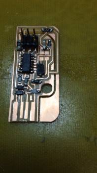
I milled out another one of the standard boards to try the process again, hopefully with more programming success. Given what I had learned from the last endeavor, the milling process took about 20 minutes this time.